Technical Guide
Explore an in-depth guide for engineers and tech professionals, providing all the details needed to replicate our data center.
By eliminating traditional air conditioning and harnessing 100% of the heat generated by its electrical components, all without having any impact on the landscape, D4 stands as one of the world's most sustainable and efficient data centers.
Infomaniak aims to make this innovation widely accessible. Rather than retaining exclusive rights, they are committed to making their heat recovery technology open-source and easily replicable across the industry. This initiative encourages other data center operators to adopt similar ethical and sustainable practices for collective environmental benefit.
This page provides a detailed guide to replicating a data center like D4. We will begin by conceptually describing the heat recovery system that serves as the primary operating mode of the data center, along with the emergency mode design, which builds on Infomaniak's experience with their previous data center, D3. Next, we will present detailed diagrams of D4, including precise measurements and key architectural characteristics. Additionally, we will outline the technical specifications of D4's components, accompanied by their respective technical sheets. Finally, we will discuss critical considerations for selecting a suitable site for constructing a similar data center.
Heat recovery system
Infomaniak's D4 heat recovery system is a pioneering solution designed to repurpose 100% of the heat generated as a byproduct by its electrical components to heat up homes in Geneva, with the projected capacity to heat up to 6,000 Minergie A-certified households annually. At full capacity, D4 will consume 14 GWh of electricity annually, generating an equivalent 14 GWh of heat per year. In Switzerland, the primary sources of residential heating are heating oil, heat pumps, natural gas, and wood. If D4's heat were to replace heating that would otherwise rely on natural gas, heating oil or wood pellets, it could prevent the release of approximately 3,388 tonnes, 4,312 tonnes or 6,440 tonnes of CO₂ emissions, respectively {1}. This is equivalent to the CO₂ emissions generated by approximately 1,694, 2,156, and 3,220 round-trip flights between London and New York, respectively {2}.
The following section provides a detailed overview of D4's heat recovery system, designed for seamless implementation in other facilities.
Concept
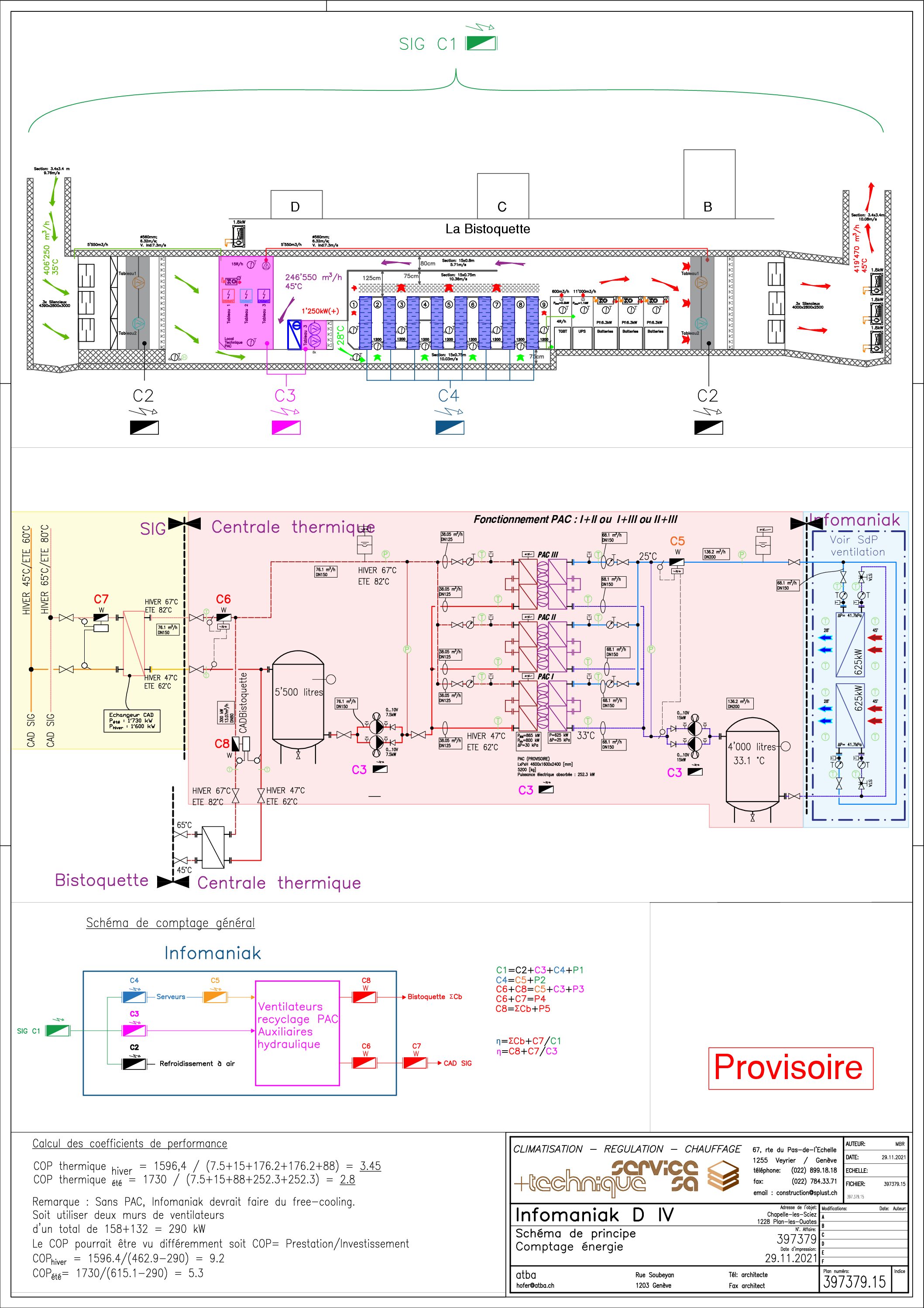
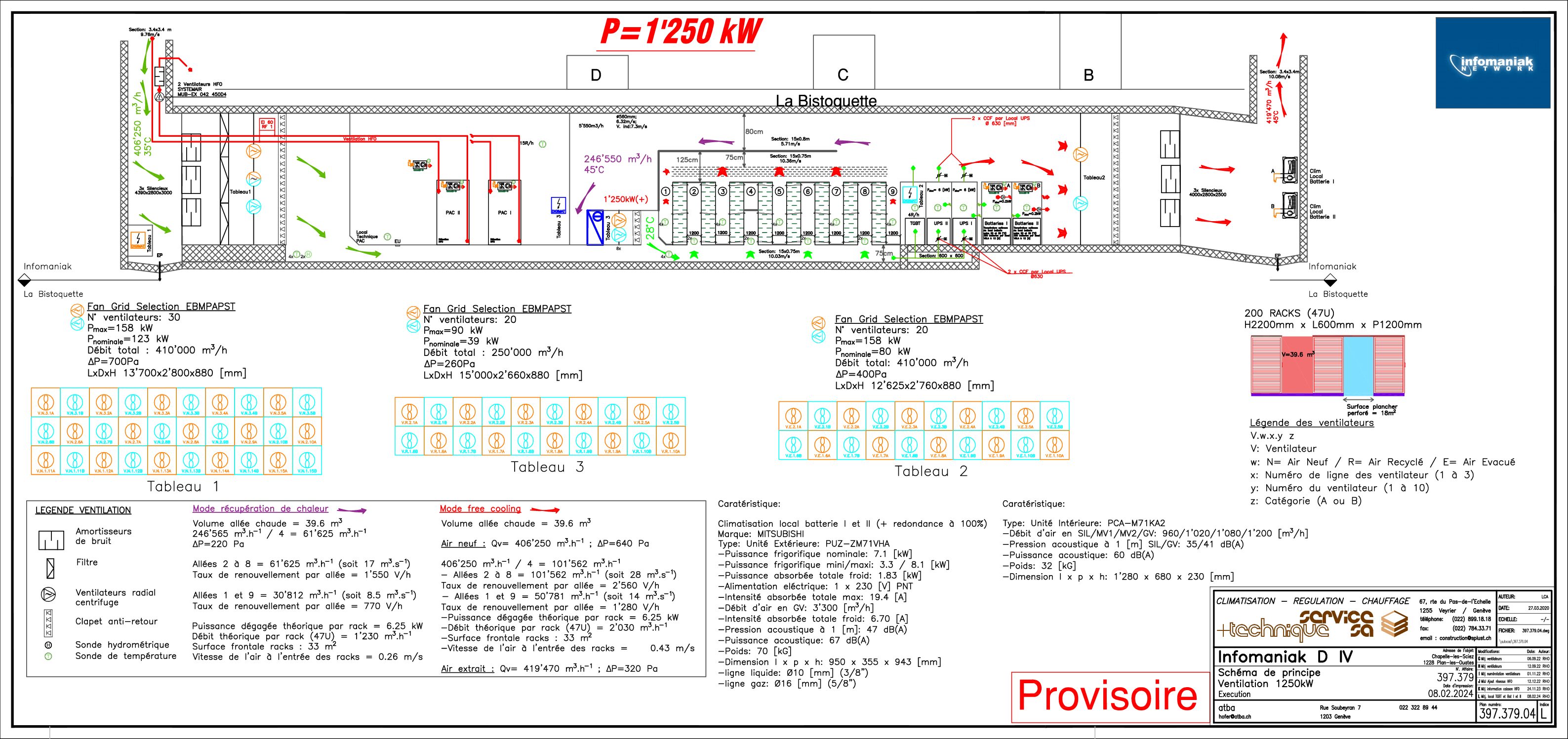
The following diagram represents a vertical cut of D4 showcasing the design of the data center.
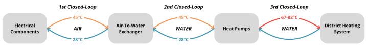
Figure 1: The 3 closed loops that make up D4’s heat recovery system.
The D4 heat recovery system operates as a closed system, meaning it is self-contained and does not exchange matter with its surroundings. It consists of three interconnected closed loops, which are systems where the working fluid continuously circulates within a sealed pathway, ensuring no external input or loss of the fluid during operation, as illustrated in the diagram below.
1st closed-loop system: from the servers to the air-to-water exchanger
Electricity powers the data center, enabling the servers to function. During operation, the servers generate heat, producing warm air at around 45°C, which is expelled into hot aisles. The warm air naturally rises toward the ceiling, and at one end of the closed-off server room, ventilators placed behind an air-to-water exchanger guide this warm ceiling air toward the exchanger. An air-to-water exchanger is a system designed to capture heat from the air and transfer it to water through a heat-conducting surface or medium. The exchanger is composed of coils within which room temperature (approximately 28°C) water flows. As the ventilators direct airflow across the room, the warm air passes through the exchanger, where the heat is absorbed into the circulating water, cooling the air to roughly 28°C in the process.
Following this heat transfer from the air to the water, the cooled air is pushed by the ventilators under the raised floor that supports the servers. The airflow creates a low-pressure area, encouraging the cooler air to flow up through perforations in the floor, accessible only in the cold aisles. This cool air goes through the intake of the servers and cools them down, absorbing heat once again, and the cycle for this 1st closed-loop system repeats.
The heat generated by the other electrical components of the data center such as UPS systems, fans, security cameras, electrical panels, etc., is also collected and directed towards the air-to-water exchanger, resulting in D4 truly reusing all the heat it generates.
2nd closed-loop system: from the air-to-water exchanger to the heat pump
Unlike the 1st closed-loop system which was based on the movement of air, this 2nd closed-loop system is based on the movement of water.
After exiting the air-to-water exchanger, the water isn’t yet hot enough for transmission to the district heating systems of Services Industriels de Genève (SIG). In order to be suitable for SIG’s district heating installations the water must be at 67°C in summer and 82°C in winter. Therefore, after being warmed by the air-to-water exchanger, the water enters the heat pumps where the gas in the heat pumps expands by absorbing energy from the water, which cools the water to 28°C. The now room-temperature water is directed to the air/water exchanger and the cycle for this 2nd closed-loop system repeats.
3rd closed-loop system: from the heat pumps to SIG’s district heating
In this 3rd closed-loop system, the district heating water flows into the heat pumps where the heat pump gas, which has expanded by absorbing the heat from the warm 45°C water that exited the air-to-water exchanger, is now compressed releasing heat and warming the district heating water to 67°C in summer or 82°C in winter.
In a heat pump, the gas releases more heat than it absorbs because of the external work done during compression. When the gas is compressed, energy is added, increasing its temperature and total energy content. This allows the gas to release not just the heat it absorbed during expansion but also the additional energy from compression. As a result, the total heat released is the sum of the absorbed heat and the work done by the compressor. This process enables heat pumps to efficiently transfer heat from a lower temperature source to a higher temperature destination.
In order to create this external work and compress the gas, heat pumps require electricity. The appeal of heat pumps lies in their exceptional efficiency: they can deliver significantly more heat than the electrical energy they consume. This efficiency is quantified by the Coefficient of Performance (COP), a measure of the ratio of heat output to electrical energy input. For instance, a heat pump with a COP of 3 can produce 3 MWh of heat energy while consuming only 1 MWh of electricity. The higher the COP, the more efficient the system. The COP depends on factors such as the temperature difference between the heat source and the destination; smaller temperature differences yield higher COP values.
In D4, the heat pumps serve a dual purpose, they are used to heat up the water from SIG’s district heating and to cool down the servers. Indeed, it is the heat pumps that cool down the water from the 2nd closed-loop system which in turn cools the air in the 1st closed-loop system through the air-to-water exchanger, which then cools down the servers.
Emergency mode
The emergency mode is implemented in the D4 because if the heat recovery mode fails for any reason or if the heat operator temporarily cannot recover the heat, we need to remove it so that the servers do not to stop functioning.
This mode is the same as what is done in the D3 as a normal functioning mode. It is using ambient temperature air to cool down the servers. This is done by having an air entry point at one side of the data center and an exit point at the other. The air is filtered to make sure that it is clean and does not contain fine particules. For simplicity reason, let us call cold air the air that comes in the data center, and call it hot air once it has passed through the servers, cooling them at the same time.
To avoid having a mix of flow between the cold and hot air, the D4 is equipped with cold and hot alleys. The cold alleys, as you may have guessed is where the cold air arrives when it enters the data center. When in the cold alley, the air passes then through the servers to cool them and become hotter in the process. When it gets out of the servers, it arrives in a hot alley, from where it is then evacuated outside the D4 through the exit point.

Figure 2: The interior of the cold aisles, the insulation is visible on the top through the glass ceiling.
The cold alleys receive the cold air from the bottom and is hermetic so that the air is forced to pass through the servers and not directly from the cold to the hot alleys, which would mess with the cooling system.
The D4 data center is equipped with adjustable lamella walls that serve a dual purpose. In normal mode, these walls retain the hot air within the closed-loop system, enhancing the efficiency of the heat recovery process. In emergency mode, they allow the cold air to flow through while regulating the temperature during winter. This prevents the internal temperature from dropping below 7°C, which could be problematic for the servers.
As we mentioned previously, the D4 is underground below a residential area. Therefore, the entry and exit points are holes in the ground of three meters on three meters. To avoid disturbing the neighborhood, there is sound soundproofing wall that is mounted before the first wall of fan and after second one. It consists of big metal plaques placed at a certain distance so that it does not let the sound come out of the inside of the data center. This allows that even when running in the emergency mode, which should happen only rarely, the neighbors are not annoyed by the sound of the D4.

Figure 3: Power distribution panel ensuring redundancy, and continuous operation in the D4 data center.
Redundancy
Data centers are renowned for their reliability, operating virtually without interruption. For clients relying on Infomaniak’s hosting services, ensuring consistent website performance is critical. To achieve an exceptionally low failure rate, the D4 data center integrates advanced redundancy features designed to prevent disruptions and maintain operational continuity.
The first of these features is the dual entry point for medium-voltage power lines. This setup ensures that if one line is disrupted, the second line can immediately take over, maintaining a stable and uninterrupted power supply to the data center.
Another vital component is the sophisticated inverter system. The D4 is equipped with two arrays of six inverters, each fulfilling two critical roles. Firstly, the inverters guarantee a clean and stable electrical signal for the servers and other sensitive equipment, protecting them from potential damage or malfunctions caused by fluctuations in power. Secondly, they continuously monitor the power supply and seamlessly switch to their integrated batteries if a disruption occurs. These batteries act as an essential bridge, providing temporary power while the backup generators come online.
In the rare event of a prolonged power outage, the D4’s resilience is further supported by three high-capacity generators fueled by an on-site tank. This setup ensures that the data center can continue to operate smoothly, even during extended disruptions, until the primary power supply is restored.
Together, these robust systems exemplify Infomaniak’s commitment to reliability, ensuring their clients experience uninterrupted service and peace of mind.
Site selection for a new data center
Selecting the site for the data center is a crucial step in the project. Designed as a model of sustainable urban infrastructure, the facility will operate without causing noise, emissions, or visual disruption by being built underground within the eco-district park. This approach preserves undeveloped land, optimizes urban space, and seamlessly integrates the data center into a multifunctional environment that benefits both the community and the local ecosystem.
A key factor in site selection is the availability of an existing district heating system, which allows the data center's heat recovery capabilities to be integrated efficiently. By locating the facility near residential areas already connected to this network, the recovered heat can be distributed to homes and businesses, improving energy efficiency and reducing reliance on traditional heating methods. The heat generated by the data center's servers will be captured and distributed using technologies compatible with district heating systems, ensuring the network can absorb and redistribute the energy continuously. For instance, the system must be capable of handling the project’s full heat capacity, estimated at 1.7 MW, without interruption.
Energy availability is another critical consideration, as seamless integration with the network ensures efficient use of recovered heat throughout the year. The flexibility to adopt different energy transfer methods, such as water-cooling systems, further enhances adaptability and sustainability.
Additionally, evaluating the local energy landscape involves analyzing the current grid capacity and identifying opportunities to optimize energy use and revalorize resources, regardless of the energy source, to enhance the data center's sustainability. Incorporating renewable energy options not only reduces the data center's carbon footprint but also enhances the overall sustainability of the regional energy system. This approach ensures that the data center's power requirements can be met without straining the existing electrical supply. By choosing a site with energy integration potential, the project supports a circular energy economy, emphasizing the reuse and recovery of energy to enhance the area’s energy efficiency and environmental goals, regardless of the original energy source.
One approach is to place facilities underground, reducing environmental and visual impacts while preserving the aesthetics and multifunctionality of urban areas. For example, embedding infrastructure beneath parks can avoid converting natural spaces into single-purpose developments.
What are the benefits of this approach?
By minimizing surface disruption, this method supports sustainable urban planning and promotes circular energy systems. Repurposing waste heat, for instance, can benefit local communities by feeding into district heating networks, improving energy efficiency, and reducing reliance on traditional energy sources. Environmental factors and biodiversity considerations are integral to the site selection process for the data center. The goal is to minimize the ecological impact of the facility and ensure its sustainable integration into the surrounding environment. This involves conducting a thorough assessment of the site’s existing biodiversity, evaluating potential disruptions to local wildlife and ecosystems, and implementing measures to protect and enhance natural habitats. By selecting a site that already supports a sustainable urban development, such as an eco-district park, the project can avoid disturbing untouched greenfield areas and instead make efficient use of multifunctional urban spaces. The data center's design prioritizes sustainability by preserving natural aesthetics and promoting biodiversity. Its integration into the surrounding environment supports eco-friendly practices, including energy recovery systems that repurpose waste heat to benefit the community. These efforts align with broader environmental and sustainability goals, ensuring both functionality and minimal ecological impact.
Evaluating land costs helps ensure the project remains within budget while selecting a location with infrastructure capable of supporting future expansion and increased energy integration. Adhering to zoning regulations is essential to avoid legal complications and accelerate the approval process. Given the rarity of industrial activities in residential zones, collaborating with local authorities and stakeholders is critical to ensure compliance and community acceptance. The zoning must not only accommodate data center operations but also support the integration of renewable energy infrastructure, such as solar panels. This often involves coordination with urban planners and local councils to align with sustainability goals while addressing regulatory constraints.
The impact of local development policies is a key factor in the site selection for the data center. Local government policies and development plans can significantly influence the feasibility and future success of the project. Favorable policies that encourage sustainable infrastructure, renewable energy integration, and heat recovery can offer tax incentives, grants, or fast-tracked permitting processes, making it more attractive to locate the data center in certain areas. Local policies promoting eco-friendly initiatives, such as district heating systems or green building certifications, can facilitate the integration of the data center's heat recovery system with the existing urban infrastructure. By aligning the project with local development goals, the data center not only supports regional sustainability targets but also positions itself as a model for future urban planning and sustainable development initiatives. Additionally, such alignment can facilitate access to financial aid or subsidies, further enhancing the project’s feasibility. Understanding these policies ensures that the project can navigate regulatory requirements smoothly while contributing to the local community’s long-term environmental and economic objectives.
In conclusion, the site selection for the new data center is a complex and multifaceted process that balances technical, environmental, and community considerations to ensure sustainable integration into the surrounding area. By prioritizing proximity to residential zones, the facility can efficiently link its heat recovery system with the district heating network, enhancing energy efficiency and reducing reliance on traditional heating methods. The commitment to using renewable energy sources and integrating with the local energy grid not only supports the region’s sustainability goals and minimizes the center's carbon footprint but also helps avoid the need for developing more polluting energy sources, such as natural gas or pellet power plants.
By integrating environmental and biodiversity considerations, the project safeguards the natural landscape and supports local ecosystems. Aligned with urban planning policies and zoning regulations, it demonstrates economic and regulatory sustainability. This data center serves as a model of sustainable infrastructure, contributing to the community’s well-being and inspiring future developments.
Technical information
I) Heat Pump
- Purpose: In D4, heat pumps raise the temperature of water, already pre-warmed by the air itself warmed by the heat generated by the data center's IT components, to a level suitable for transmission to SIG's district heating systems. The heat pumps also function as the data center's cooling mechanism.
- Brand and Model: Trane XStream™ RTWF Water-Cooled Liquid Chillers.
- Type: Water-cooled chillers with screw compressors designed for indoor installation.
- Capacity Range: 334–1,811 kW, depending on the configuration and refrigerant.

Figure 4: One of the two heat pumps.

Figure 5: The air-to-water exchanger is on the right of this picture, the wall of ventilators is on the left.
II) Air-To-Water Exchanger
- Purpose: The air-to-water exchanger transfers heat from warm air, generated by the data center's IT components, to the water that feeds into the heat pumps.
- Brand: D.B.M. SpA a Socio Unico
- Find the rest of the information in the technical sheet, only one page.
III) Ventilators
- Purpose:
- In the heat recovery system, ventilators guide the airflow, directing warm air to the air-to-water exchanger before circulating it back to cool the servers.
- In emergency mode, ventilators draw outside air, direct it towards the servers for cooling, and then expel it, ensuring efficient temperature regulation.
- Brand and Model: ebm-papst RadiPac EC Radial Module (Model: K3G800-PT13-01).
- Type: EC radial fan module with single-sided intake and cube construction.
- Key Dimensions:
- Rotor size: 800 mm.
- Motor size: 200 mm.
- Electrical Specifications:
- Voltage: 380–480 VAC, 3-phase.
- Frequency: 50/60 Hz.
- Power consumption: 8.04 kW at maximum performance.
- Current draw: 12.3 A.
- Performance:
- Maximum airflow: 21,135 m³/h.
- Static pressure rise: 924 Pa.
- Efficiency: 69.9% (total system efficiency).

Figure 6: Cooling fan system ensuring optimal airflow and temperature regulation in the D4 data center.

Figure 7: Ventilators wall.


Figure 8: Backup battery system providing critical power continuity during outages.
IV) Batteries
- Purpose: Batteries in a data center ensure uninterrupted power supply, stabilize voltage, and bridge power gaps during outages.
- Brand and Model: EnerSys® DataSafe® HX+ Valve Regulated Lead Acid (VRLA) Battery (Model: 12HX560FR+).
- Key Specifications:
- Nominal voltage: 12V.
- Power output: 560 Watts per cell at 15-minute rate to 1.67Vpc at 77°F (25°C).
- Design life: 10–12 years.
- Operating temperature: -4°F (-20°C) to 113°F (45°C).
- Internal resistance: 3.30 mΩ.
- Short-circuit current: 3,800 A.
- Physical Dimensions:
- Length: 13.3 in (338 mm).
- Width: 6.8 in (173 mm).
- Height: 10.7 in (273 mm).
- Typical weight: 98.5 lbs (44.7 kg).
V) Inverters
- Purpose: An inverter in a data center converts DC power from backup batteries or renewable sources into AC power to ensure uninterrupted operation of equipment during power outages or fluctuations.
- Brand and Model: ABB MegaFlex DPA (Dynamic Power Architecture) UPS.
- Power Range: 250 kW to 1,500 kW.
- Key Features:
- Modular architecture with 250 kW modules.
- Scalability: Can support up to 6 modules for a total of 1,500 kW.
- High efficiency with online double-conversion topology (VFI-SS-111).
- Transformer-less design for compactness and efficiency.
- Electrical Specifications:
- Input voltage: 380/400/415 V, 3-phase, 50/60 Hz.
- Output voltage: Same as input.
- Efficiency: High operating efficiency, reducing energy costs.
- Protection rating: IP20.
- Dimensions and Weight:
- 1,000 kW system: 2,235 mm (L) x 2,000 mm (H) x 1,200 mm (D), 1,950 kg.
- 1,500 kW system: 3,045 mm (L) x 2,000 mm (H) x 1,000 mm (D), 2,945 kg.
- Individual module: 356 mm (L) x 1,824 mm (H) x 1,000 mm (D), 350 kg.

Figure 9: Uninterruptible Power Supply (UPS) system ensuring stable and reliable power for critical infrastructure.

Figure 10: This picture shows the alternator.
VI) Alternator
- Purpose: An alternator in a data center generates AC power by converting mechanical energy from a backup generator into electrical energy to supply power during outages.
- Brand and Series: LINZ Electric SL and PRO Series Alternators.
- Type: Brushless, 4-pole alternators with exciter and electronic voltage regulation.
- Electrical Specifications:
- Voltage Regulation: ±1% static error.
- Frequency: 50Hz or 60Hz operation, switchable.
- Power Output: Rated for various applications under cos φ = 0.8 and ambient temperature up to 40°C.
- Protection: IP23 as standard.
- Insulation Class: Class H for rotor and stator windings.
- Ventilation: Axial with air intake from the non-drive end.
VII) RSK Non-Return Valve
- Purpose: An RSK non-return valve in a data center prevents backflow in drainage or cooling systems, ensuring unidirectional flow to protect equipment and maintain system efficiency.
- Type and Material:
- Fully constructed from stainless steel (1.4301 or 1.4571).
- Frame made from C-profile galvanized steel or aluminum, bolted at corners without any welding.
- Suitable for all standard duct connections.
- Dimensions:
- Connection flange widths: 25 mm, 36 mm, or 50 mm.
- Body depth: 165 mm.
- Blade width: 100 mm with EPDM gaskets.
- Design Features:
- Rigid hollow-profile blades with interchangeable EPDM seals, resistant to temperatures up to 80°C.
- Equipped with additional side seals.
- Axes made of aluminum, securely inserted into hollow sections of the blade profile.
- Supported on both sides with either:
- Ball-bearing joints (steel).
- Oil-impregnated sintered bronze plain bearings.
- Mounting Configurations:
- Suitable for both horizontal and vertical airflow directions.
- Horizontal airflow requires horizontal blade orientation.
- Mounting direction must be specified during ordering.
- Optional Features:
- Gas-tight external casing.
- Interior mineral fiber insulation with a thermally separated secondary casing.
- Axes supported by articulated ball bearings.
- External linkage for blade operation.
- Anodized or powder-coated finish.
- Material certificates in compliance with EN 10204-3.1.
- Seismic calculations and factory inspections available.
- Additional accessories:
- Grilles.
- Limit switches.
- Sealing class options: ~ CEN 1751 class 2.
- Extended temperature resistance:
- 80°C (standard).
- 200°C or 600°C (optional).

Figure 11: Filters are shown on the right of the picture.

Figure 12: Close-up picture of the filters.

Figure 13: Filters are shown on the left of the picture.
VIII) Filters
- Purpose: In emergency mode, when the data center relies on outside air for cooling, filters are used to remove fine particles and contaminants, ensuring clean air reaches the servers to prevent damage.
- Product Type: Premium Wave Pocket Filters (PW-XX-46-7 ePM1 70% HoKu®-XP).
- Material and Construction:
- Media Material: Polyester/Polypropylene (PES/PP).
- Frame Type: HoKu®.
- Media Color: White.
- Fire Resistance:
- DIN 53438: F1.
- DIN EN ISO 11925-2: E.
- DIN 4102: B2.
- Maximum Operating Temperature: 80°C.
- Performance Specifications:
- Filtration Efficiency:
- ISO 16890 Classifications:
- ePM1: 70%.
- ePM2.5: 77%.
- ePM10: 92%.
- Coarse: >99%.
- Previous Standard (EN 779:2012): F7.
- Pressure Drop:
- Initial Pressure Drop: 74 Pa.
- Final Pressure Drop: 300 Pa.
- Burst Pressure: >600 Pa.
- Dust Holding Capacity: 799 g.
- Airflow Rate: 3,400 m³/h.
- Filtration Efficiency:
- Energy Efficiency:
- Eurovent RS 4/C/001 Classification: A.
- Energy Consumption: 1,054 kWh/year (at 6,000 operational hours annually).
- Energy Cost: 211 CHF/year.
- Dimensions and Sizes:
- Filter Dimensions (Width x Height x Depth in mm):
- PW-66-46-7: 592 x 592 x 460.
- Options available for smaller/larger configurations:
- 490 x 592 x 460.
- 287 x 287 x 460.
- 892 x 592 x 460.
- Surface Area: 13.50 m² for PW-66-46-7.
- Number of Pockets: 10 (standard model).
- Key Features:
- Progressive media design for improved filtration efficiency.
- High resistance to dust accumulation and optimized airflow.
- Tested for durability and consistent performance under varying conditions.
IX) Diesel Engine
- Purpose: The diesel engine serves as the backup power generator for the data center, providing reliable electricity during power outages to ensure continuous operation.
- Brand and Model: Rolls-Royce MTU 2000 Series Diesel Engines.
- Key Specifications:
- Power Output:
- 12V: 665–716 kW.
- 16V: 709–998 kW.
- 18V: 887–1097 kW.
- Speed: 1500–1800 rpm, 50/60 Hz configurations.
- Cooling Method: Turbocharged with charge-air cooling.
- Combustion: Direct injection.
- Cylinder Configuration: V-configuration, 90° angle.
- Power Output:

Figure 14: Diesel engine powering the backup generator to ensure reliable energy supply during outages.

Figure 15: MSA baffle silencers ensuring effective noise reduction.
X) MSA Baffle Silencer
- Purpose: The MSA Baffle Silencer is used to block noise, allowing the data center to operate quietly in an urban area without causing disturbances to the surroundings.
- Type: Rectangular baffle silencers designed for airflow and noise reduction in HVAC systems.
- Core Functionality:
- Noise Attenuation: Reduces noise through absorption and resonance.
- Frequency Target: Ideal for reducing critical low-frequency sounds produced by fans.
Diagrams of the data center
Footnotes:
- Minergie A: A Swiss certification standard for energy-efficient buildings, with the "Minergie A" designation indicating the highest level of energy performance.
- Wood Pellets (CN vs NCN): The emissions factor for wood pellets excludes carbon offsets during tree growth. - Not Carbon Neutral (NCN): 6,440 tCO₂. - Carbon Neutral (CN): Accounting for offsets reduces avoided emissions to 784 tCO₂.
- References:
- Eleonora Lo Vullo, Fabio Monforti-Ferrario, Valentina Palermo, and Paolo Bertoldi. Greenhouse gases emission factors for local emission inventories, Covenant of Mayors databases - version 2022, 2022. https://ec.europa.eu/jrc
- MyClimate. CO₂ calculator for portfolios. https://co2.myclimate.org